Continuing investigation into the Negative Impacts of sub-optimised part design, this week we look at Weld Lines in plastic injection moulded parts as part of your Design for Manufacture Process.
A designer needs to be ever mindful that seemingly minor design details can have a significant impact on the productivity, efficiency and therefore competitive advantage of an injection moulded part and its success out in the market.
A weld line, also called a meld line, in plastic injection mouldings is a visible line or seam on the surface of the moulded part where two or more flows of molten plastic meet, knit/weld together and solidify.
This defect can occur in several ways;
Characteristics of Weld Lines:
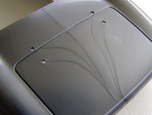
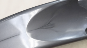
Appearance: Weld lines typically appear as lines or seams on the surface of the part, often in areas where the plastic flow fronts intersect. They can sometimes be faint but may also be more pronounced depending on the processing conditions and material and surface finish used.
Location: They are often in areas where the flow of molten plastic has to change direction or meet after a core pin or thin section or multiple melt fronts from multiple gates.
Causes of Weld Lines:
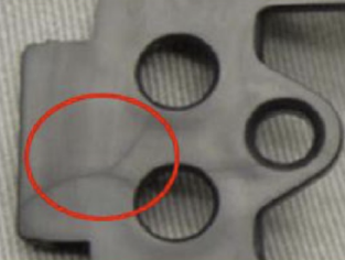
Size and Location of holes: In terms of melt front flow, when ever there is a feature in the design like a hole in the part that requires a pin in the tool, a separation or splitting of the weld front will occur. After the hole, in the direction of flow, the split weld fronts will re-join causing a weld line.
Thin wall sections: A localised thinning of the wall section in the part design that may impede the uniform flow through this area of the tool. The material slows in this spot causing ‘Race Tracking of the adjacent material flow that sweeps around it. When the split weld fronts meet down stream a weld line can occur.
Inadequate Mould Design: Poorly designed runner systems or gates can lead to flow fronts meeting inappropriately, resulting in weld lines.
Injection Speed and Pressure: Low injection speed or pressure can prevent the proper fusion of the plastic flows, leading to weak weld lines.
Temperature Variations: If the temperature of the molten plastic varies significantly, it can affect how well the different flow fronts weld together.
Venting Issues: Insufficient venting in the mould can cause air entrapment or irregular flow patterns, leading to weld lines.
Material Properties: Certain materials are more prone to weld lines due to their specific flow characteristics or cooling rates. Materials with metallic pigments are extremely suspected to welds as the particles align along flow lines and highlight weld lines.
Implications of Weld Lines:
Mechanical Properties: Weld lines can create weak points in the moulded part, potentially affecting its structural integrity and overall strength.
Aesthetics: They can be visually unappealing, particularly in parts where a smooth surface finish is desired.
Functional Issues: In some applications, weld lines can interfere with the part's performance or functionality, especially if they compromise strength or create potential failure points.
Mitigating Weld Lines:
Optimise Part Design: Ensure that your part has uniform wall sections and only design enclosed holes where necessary.
Injection Point location: Place you injection point into or as close to the largest hole in a part. Holes are often essential for part function and can not be avoided. Generally, the larger the hole the greater the weld line. The further the hole is from the gate the more prominent the weld line will be as the melt front temperature drops and pressure subsides as the front travels away from the gate.
Optimise Mould Design: Improve the design of runners, gates, and vents to ensure more uniform flow and better fusion of the plastic.
Adjust Processing Parameters: Increase injection speed and pressure, or adjust mould temperature settings to enhance the fusion of the flow fronts.
Use Flow-Improving Materials: Some materials are formulated to minimize weld line issues and improve overall flow characteristics.
Check Mould Venting: Ensure that the mould is properly vented to avoid air entrapment and facilitate better flow.
By addressing these factors, you can reduce the occurrence and impact of weld lines in plastic injection moulding.
So how do you minimise or eliminate weld lines from your parts?
Apart from the considerations above, choose a reliable high quality tool maker and moulder. Build an open communicative relationship whereby they have input in the design of the part. Design is a journey and toolmaking and moulding is an integral part along the way rather than an end point where a design is thrown over the wall to NPI and production.

Perform DFM (Design for Manufacture) as part of the design process, not simply a check box prior to release. Mould flow analysis is an integral part of your DFM and should be performed periodically through the evolution of the part design.
Weld lines are a part of the moulding process. Designing to minimising or eliminating them will lead to a more productive, efficient and high quality outcome for your customers.
---
équipe design & consulting , with 20 years experience in design and manufacture of Medical grade moulded parts and product, including 5 years at the coal face as Operations Manager at a world class medical grade moulding facility; we are specialist in Design for Manufacture (DFM).
Please reach out if you feel you need assistance with your part design for plastic injection moulding, from Design Coaching and Guidance to Full Service Design Consulting.
www.equipedesign.au#Designforplasticinjectionmoulding #DesignForManufacturing #DesignThinking #DesignforManufacture #DesignConsulting #DesignCoaching #equipedesign #DesignforAssembly #IndustrialDesign #CREODesign
Comments