Plastic injection moulding is a cornerstone of modern manufacturing, enabling the production of high-precision, complex parts with efficiency and scalability.
Whilst the advancements and design freedoms in Additive Manufacturing cannot be ignored, it is still yet to achieve the productivity, and in some cases, accuracy and quality of injection moulding.
For injection moulding to retain its competitive advantage, though, a critical but often overlooked element of this process is the ejection system.

Once the molten plastic part has cooled and solidified in the mould, it must be removed without damage to the part or the mould itself. This is where the ejection system plays an essential role.
It is also where an understanding the of the ejection system and its capabilities, traps and pitfall, but also possibilities, can free up your design process and the design itself for the most optimised product design outcome.
Ejection systems vary based on the type of part being produced, the complexity of the mould, and the specific requirements of the application.
We will explore the different types of ejection systems used in plastic injection moulding, examining their mechanisms, applications, and advantages to assist you enhance your designs for the benefit of your end users, customers, company and/or clients.
What is Line of draw (LOD) and how does it impact ejection.
To to investigate Part Ejection, one must have a basic knowledge of the design principles of part and tool design and the moulding process. One area of most significance for ejection is ‘Line of Draw’ or LOD.
The line of draw in plastic injection moulding refers to the primary direction in which the mould halves (core and cavity) separate during the opening phase, allowing the part to be ejected. It represents the straight path that follows the movement of the mould's mechanical components when the mould opens or closes.

Key Characteristics of the Line of Draw:
Alignment with Part Design: For ‘Open n Shut’ parts, it's features must be designed to avoid undercuts or obstructions along the line of draw to ensure smooth moulding and ejection. No-one likes a one shot tool. This is where the yelling starts.
Critical for Ejection: Proper alignment ensures that the part can be ejected without damage or interference.
Draft Angles: Parts typically designed include draft angles (slight tapers) on surfaces parallel to the line of draw to facilitate easy ejection and avoid sticking.
Understanding and defining the line of draw is essential for part designers and mould designers, as it directly impacts the manufacturability, quality, and efficiency of the moulding process and the parts it produces.
The Ejector System
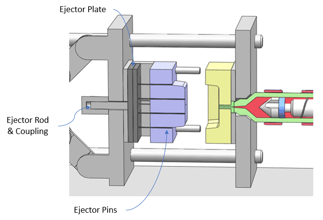
The ejector system commonly comprises of an hydraulically or electrically driven ejector rod in the moulding machine. This rod is connected to the ejector plates via a 'ejector coupling'. The ejector plates then are connected tot he ejectors.
When ejection phase is activated after tool opening, within the moulding cycle, the rod is advanced forwards, in turn moving the plates that act upon the ejectors.
Types of Ejection System
1. Pin Ejection System
The pin ejection system is the most common and straightforward type of ejection mechanism. It uses ejector pins strategically placed within the mould to push the part out of the cavity. These pins are typically cylindrical and move linearly through holes in the mould plate.

Mechanism:
After the mould opens, a hydraulic or mechanical system in the moulding machine, connected via ejector rod and coupling activates the ejector plate, which pushes the ejector pins forward.
The pins contact the part and push it out of the mould cavity.
Applications:
Used for parts with simple geometries and uniform surfaces that are designed to eject in the ‘Line of Draw” (LOD).
Suitable for parts where pin marks can be tolerated or are in non-critical areas.
Advantages:
Simple design and easy to implement.
Cost-effective and reliable for a wide range of parts.
Many pin sizes and materials are available in a range of diameters off the shelf. These are then machined to the shape of the surrounding cavity.
Limitations:
May leave visible marks on the surface of the part.
Not ideal for parts with intricate or delicate features.
2. Blade Ejection System
The blade ejection system employs thin, flat blades instead of cylindrical pins. These blades are used when parts have narrow slots or thin features that pins cannot effectively reach.

Mechanism:
The blades are embedded into the mould and operate similarly to pins, moving linearly to eject the part.
They provide support along flat surfaces or edges to avoid deforming thin sections.
Applications:
Ideal for parts with thin walls, slots, or flat surfaces requiring support during ejection.
Commonly used in electronics and consumer goods manufacturing.
Advantages:
Reduces the risk of deformation or damage to thin features.
Provides a more uniform ejection force for delicate parts.
Limitations:
More complex to design and maintain compared to pin systems.
Require a wire cut hole rather than drilled during tool fabrication.
Requires precise alignment to avoid damaging the part or mould.
3. Sleeve Ejection System
Sleeve ejection systems use hollow, cylindrical sleeves that encircle a core pin to eject tubular or cylindrical parts. This system is ideal for parts with internal features, such as holes or hollow sections.

Mechanism:
The sleeve moves forward along the core pin, pushing the part out of the cavity.
It ensures even force distribution along the cylindrical surface of the part.
Applications:
Commonly used for parts like caps, containers, and bushings.
Suitable for parts requiring precise handling of internal features.
Advantages:
Provides consistent and even ejection for cylindrical parts without the impact of a point load of an ejector pin.
Minimizes the risk of damaging internal features.
Limitations:
More complex and costly to implement than pin systems.
Requires additional machining and alignment efforts.
4. Stripper Plate Ejection System

Stripper plate systems use a plate that moves parallel to the mould surface, pushing the part off the core or cavity. This method is particularly useful for large, flat parts or parts with delicate features.
Mechanism:
A stripper plate is installed between the mould core and cavity.
As the mould opens, the plate moves forward, uniformly ejecting the part.
Applications:
Ideal for parts with complex geometries or fragile edges.
Common in automotive and large appliance manufacturing.
Advantages:
Provides uniform ejection across the entire part surface.
Reduces the risk of deformation or uneven ejection forces.
Limitations:
More expensive and complex to design and manufacture.
Requires careful calibration to avoid part damage.
5. Air Ejection System
Air ejection systems use compressed air to release parts from the mould. This non-contact method is suitable for lightweight or delicate parts that may be damaged by mechanical ejectors. This may also be used for flexible parts like thin walled silicone LSR where pin
style ejection is not feasible.
Mechanism:
Compressed air is directed through small channels or vents in the mould.
The air pressure gently pushes the part out of the cavity.
Applications:
Common for thin-walled or lightweight parts.
Used in medical and precision engineering industries.
Advantages:
Eliminates mechanical contact, reducing the risk of damage.
Ideal for delicate or precision parts.
Limitations:
Limited force makes it unsuitable for larger or heavier parts.
Requires precise mould design to ensure effective air flow.
6. Angled Ejection Systems or Angled Lifters:
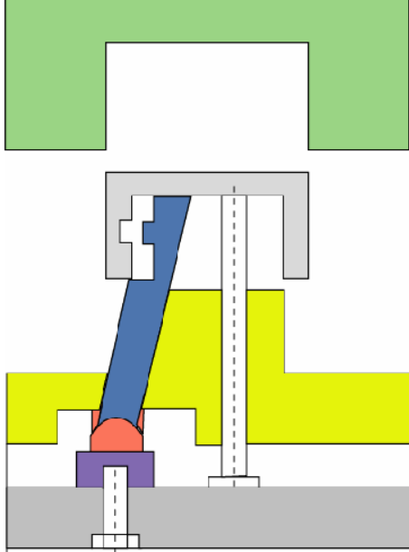
Mechanism:
The angled ejection system uses transverse ejector actions or movements across the lines of draw to remove the part from the core.
Applications:
For demoulding complex part designs that require features that are formed across the LOD for enhanced fit form or function.
Advantages:
Minimises the need for mechanical or hydraulic slides.
Facilitates complex designs enabling moulding of parts with undercuts, angled surfaces, or intricate geometries that cannot be ejected straight along the line of draw.
Precision and Repeatability. With proper design and maintenance, angled ejection systems offer consistent and accurate performance across high production volumes.
Limitations:
Increased Complexity and integrating angled lifters or ejection systems adds complexity to the mould, requiring advanced engineering and expertise.
Higher Manufacturing Costs of additional components such as cams, lifters, and precision-guided mechanisms increase the cost of mould fabrication.
Maintenance requirements of angled systems involve moving parts that are prone to wear and require regular maintenance to ensure smooth operation.
Space Constraints with the inclusion of angled lifters or mechanisms can increase the mould's size and complexity, making it less compact.
7. Custom Ejection Systems
Custom ejection systems are tailored to specific parts or mould designs, often combining multiple ejection methods outlined above. These systems are developed to address unique challenges, such as complex geometries, delicate features, or high production demands.
Mechanism:
A combination of pins, plates, air, vacuum or angled systems is used.
Advanced sensors and actuators may be incorporated for precision.
Applications:
Suitable for specialized industries like aerospace, medical devices, and automotive components.
Advantages:
Offers maximum flexibility and adaptability.
Optimized for specific part requirements.
Limitations:
Higher design and manufacturing costs.
Increased complexity in maintenance and operation.
The ejection system is a critical component of the plastic injection moulding process, ensuring that parts are removed efficiently and without damage. From the simplicity of pin ejection to the sophistication of custom systems, product designers and mould manufacturers have a wide range of options to suit various applications and part designs.
Understanding the strengths and limitations of each ejection system helps both product designers and mould manufacturers make informed decisions, optimising production efficiency and product quality.
As technology advances, innovations in ejection systems continue to enhance the capabilities of plastic injection moulding, paving the way for even greater precision and efficiency and enhancing your product designs.
---
équipe design & consulting is a Product Design Consultant in Sydney
with 20 years experience in design and manufacture of Medical grade moulded parts and product, including 5 years at the coal face as Operations Manager at a world class medical grade moulding facility; we are specialist in Design for Manufacture (DFM).
Please reach out if you feel you need assistance with your part design for plastic injection moulding.
We offer Design Coaching and Guidance to Full Service Design Consulting.
#Designforplasticinjectionmoulding #DesignForManufacturing #DesignThinking #DesignforManufacture #DesignConsulting #DesignCoaching #equipedesign #DesignforAssembly #IndustrialDesign #CREODesign
References: ChatGPT, boyanmfg.com, google images
Comments